Pics!
Here is where I started today:

The wastegate was stuck...

So following Andy2's advice, I slide hammered those heat shields out of there! Here is what it looked like when they came out... lots of carbon built up:

The wastegate passages are kind of interesting. The gasses flow in toward the wastegate. Could the wastegate really get a good seal on this valve seat???

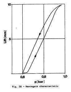
Some wastegate measurements:
wastegate valve seat ID: 24mm
wastegate valve head diameter: 31mm
wastegate installed travel/pre-load: 2mm
pressure to reach 2mm travel: 10 psi (approximate. Note: it is very "sticky" when completely closed.)
max travel: 10mm (8mm travel from touching the valve seat)
pressure to reach max travel: approx 14 psi
These wastegate pressure measurements pretty closely match what is published in the SAE paper:
Some detail of the turbine wheel. The vanes look pretty aerodynamic. I am impressed overall with the quality of this KKK turbo...

Turbine wheel specs:
OD: 59mm
exducer bore diameter: 49.5mm
thickness of fin section: 21mm
Compressor section "GW" before disassembly:

Here is what the inside of the compressor housing looks like:

Diffuser style is like most modern turbos, a parallel wall diffuser. The outer wall looks like a separate piece of metal that is pressed into the main housing.
Compressor wheel is a backward curved impeller type. This allows for more efficiency although less pressure ratio capability. Detailed shot:

The measurements of the compressor wheel are:
inducer bore: 37.5mm
OD: 60.5mm
And here is what the cartridge looks like (AKA the "guts" of the turbo...) A large colored o-ring seals the compressor housing to the cartridge.

I also tried to get some measurements necessary to calculate the turbine housing A/R ratio...

This thickness of 8mm was measured at a 59mm diameter.

 Topic: KKK K24 Turbo disassembly (Read 61657 times)